While dental technology has changed impression making considerably, areas remain that are in need of significant improvement. In particular, making impressions of multiple implants is still a difficult task to accomplish. Researchers from the Faculty of Odontology at Complutense University of Madrid in Spain and the Clinic for Fixed and Removable Prosthodontics and Dental Materials Science at the University of Zurich in Switzerland are confident that they have found a feasible solution.
It involves the use of stereophotogrammetric technology, which uses photos from different angles to map the points of an object in 3D. "Stererophotogrammetric technology is a viable, accurate, and easy technique for making multiple implant impressions," the researchers wrote in their study (Journal of the American Dental Association, April 2014, Vol. 145:4, pp. 338-344).
Highly accurate impressions are key to the correct adaptation between the prosthesis and the implants and are made at the abutment or implant level. The researchers noted that three techniques are employed for both of them: transfer, pickup, and snap-on. There are differences in approach, based on the type of materials employed.
Dentistry's digital revolution produced new methods of impression taking: indirect and direct, whereby the cast is scanned or one is created with an intraoral scanner, respectively. A number of scanning systems have hit the market, but they have limitations. "According to reports of in vitro and in vivo studies, this new generation of intraoral scanner seems to be capable of making accurate digital impressions of teeth, but these scanners do not produce reliable impressions of multiple implants when they are distributed along the whole arch," the researchers explained.
Meanwhile, photogrammetry has been producing highly accurate 3D images in other fields, such as naval engineering and topography. Stereophotogrammetry, "a more sophisticated alternative" where the points of an object are estimated, had yet to be applied in dentistry, they wrote. They applied it to three clinical situations, explained how to get stereolithographic (STL) files of the implant positions, and how to use them to fabricate computer-aided manufacturing (CAM) milling frameworks.
“A stereophotogrammetry device was used for the first time ... for obtaining impressions of implants.”
"In our case series, a stereophotogrammetry device was used for the first time, to our knowledge, for obtaining impressions of implants," the researchers wrote.
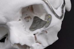
In the first case, the researchers saw a 55-year-old patient with no medical issues and six implants in her anterior mandible securing the titanium-grade V framework of her prosthesis. To obtain the first STL file, the researchers screwed in four healing abutments that were 4 mm in height into the implants and obtained alginate impressions of the maxilla and mandible. After pouring the impression in plaster, it was scanned by a lab technician.
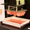
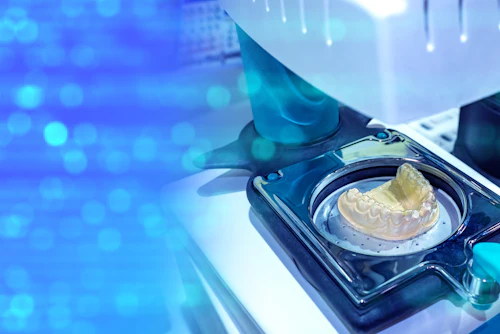
To get their second STL file, they employed a stereophotogrammetry system consisting of a laptop with computer-aided design (CAD) software (PIC Pro, Position Implants Correctly [PIC] Dental), black flag-shaped abutments with each identified by unique markings (PIC Abutment, PIC Dental), and an extraoral stereo camera with an infrared flash (PIC Camera, PIC Dental). The photogrammetry device takes 64 pictures per second to identify the special position of the implant without touching it, the researchers wrote. Then final set information about the main vectors, angles, and distances of the implants are stored in an STL file, which is called a PIC file.
In this procedure, the researchers noted the implant and abutment types that were going to be used, and then screwed in six PIC Abutments into the abutments (synOcta, Straumann). Then the area was scanned with the PIC Camera 20 cm from the patient's mouth. Then the researchers merged the first STL file with the PIC file with a best-fit algorithm. Then they merged the image again with the digital model of the soft tissues from the plaster model, yielding the 3D digital master model, the researchers explained.
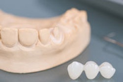
A lab technician considered the prosthetic space available using the previous scan and a bit registration taken with the provisional prostheses and, using software to build a digital framework base, the design was completed and sent to the dental laboratory electronically. There, the lab milled a titanium framework, which was tested by the researchers.
"The dentists rated the passive fit between the framework and the implants highly," the researchers wrote. "They noted no tension, misfit, or lack of adaptation." After the resin teeth were added and the patient approved of the test fit, the prosthesis was screwed into the patient's mouth, followed by three-month, six-month, one-year, and two-year follow-up appointments where no issues were noted.
In the second case, the subject, a 55-year-old man needed four implants rehabbed. The researchers started by getting a 3D STL file (PIC file) of the implants with photogrammetry. They also made an alginate impression of the healing abutments and poured it in plaster. The second STL file was obtained by using an extraoral scanner on the plaster model. Then the files were merged to create the virtual master model.
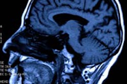
The researchers took a different approach to the virtual design of the framework in this case, using cone-beam CT (CBCT) to scan the provisional removable prosthesis. Then the lab technician "incorporated the Digital Imaging and Communication in Medicine (DICOM) file as a virtual mock-up into the previously merged STL file," they wrote. "This allowed the laboratory technician to create the framework without the need to make a denture base."
The framework fit without issue during the same recall schedule.
In the last case, a 36-year-old patient requested a fixed rehabilitation for his eight tissue-level implants in the maxilla and six implants in his mandible. The procedure was similar, except the researchers opted not to make an alginate impression and instead used an intraoral scanner to obtain STL files that would be merged along with the ones obtained with the extraoral stereoscopic camera. The final file was used to design and mill the framework. After completion, no issues were noted during the recall appointments.
The need for a second image is the most significant drawback of the photogrammetry system. It "generates information from x, y, and z points with a fixed relation to the rest of the points so the data are interrelated and cannot be separated," the researchers explained. "The STL file that is generated this way contains information about the exact position of all the implants, but it does not contain information about ... existing teeth or soft tissues."
There are "systemic mistakes" in the stitching process of an intraoral scanner when it creates an STL file, the researchers wrote. The combination of these STL files, or files from extraoral or CBCT scans, can produce more-accurate 3D models.
There are other advantages in addition to accuracy, according to the researchers. The time spent during the procedure of the first two cases was less than a conventional pickup splinted technique. They also noted that the procedure was "more comfortable for patients and easier for the operators than are other conventional or digital impression methods."
Most important, "the use of an intraoral stereophotogrammetry system allowed us to locate the precise 3D position of implants to create an accurate CAD/CAM framework, providing accurate passive fit and minimizing the possibility of post-treatment complications," they wrote.